
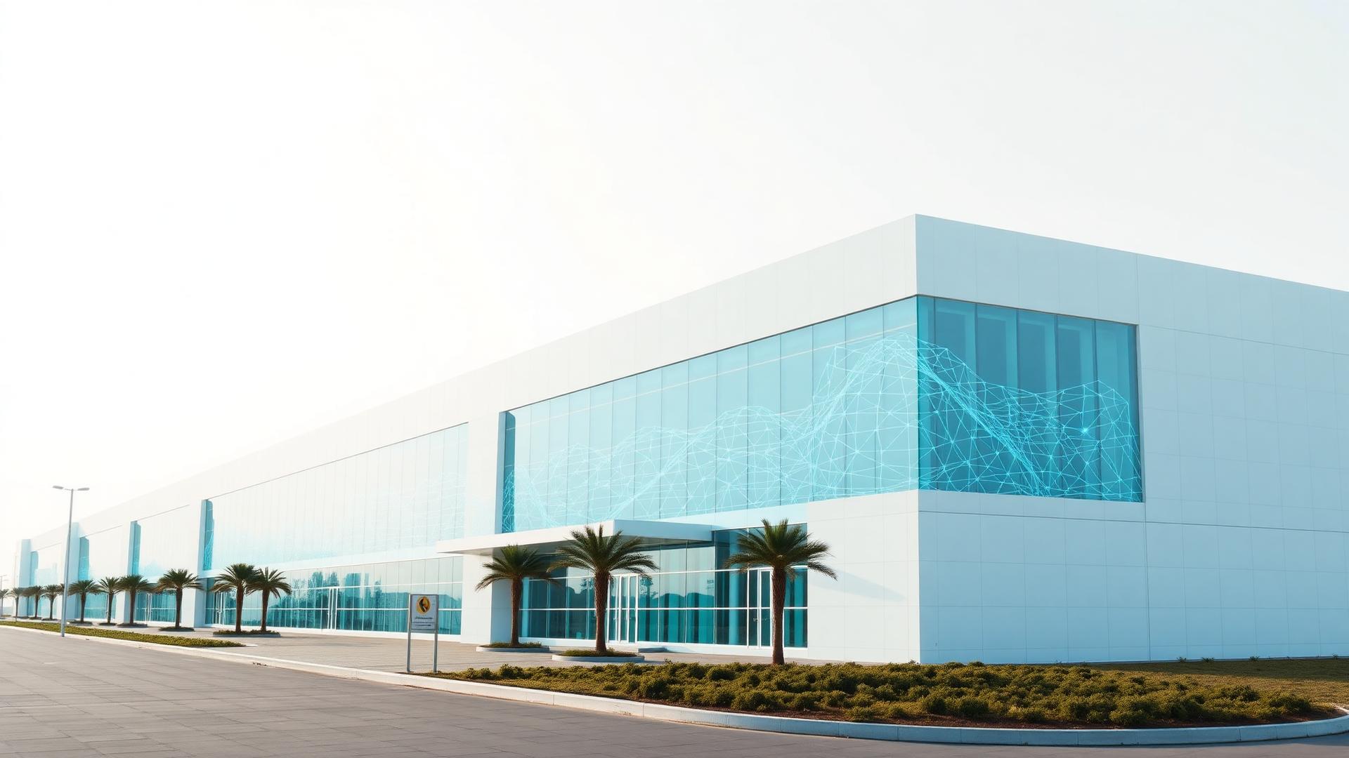
Data Center Solutions
From Blueprint to Intelligent Infrastructure
TECH21 delivers end-to-end engineering solutions for conventional, mission-critical, cloud, edge, hyperscale and AI-ready data centers — from feasibility and location selection to engineering, construction, technology integration, commissioning and lifecycle support.
Overview
One partner — complete data center lifecycle
TECH21 coordinates every multidisciplinary infrastructure package from concept through operation, under a single plan, schedule and point of accountability.
Strategy
Feasibility
Site Selection
Concept Design
Detailed Engineering
BIM / Digital Twin
Procurement
Civil Construction
MEP Installation
ICT Integration
Testing
Commissioning
Migration
Operations
Maintenance
Optimization / Expansion
Data center types
Every facility class, engineered to purpose
From enterprise halls to GPU-dense AI factories and rapidly deployable modular facilities.
Traditional / conventional
Enterprise data centers using established hot/cold aisle, UPS, generators, precision cooling and structured cabling architecture.
AI data centers
GPU-intensive infrastructure: NVIDIA/AMD GPU clusters, HPC architecture, GPU fabric, InfiniBand, 100G–800G Ethernet, RDMA, NVMe and object storage, parallel file systems, high-density power and advanced cooling.
HPC data centers
High performance computing for research, universities, government, engineering simulation, oil & gas, scientific computing, digital twins and ML.
Hyperscale
Large-scale infrastructure for cloud providers, telecom operators, government cloud, AI infrastructure and digital platforms.
Colocation
Multi-tenant environments with secure cages, private suites, Meet-Me Rooms, cross-connects, carrier-neutral infrastructure, metering and DCIM.
Enterprise
For banks, healthcare, government, universities, industrial organizations and corporations.
Edge
Distributed low-latency facilities for 5G, IoT, smart cities, industrial automation, CCTV analytics, AI inference, CDN and telecom.
Micro data centers
Small self-contained infrastructure deployed close to the applications it serves.
Modular
Prefabricated, rapidly deployable modular data center solutions with scalable capacity blocks.
Containerized
Container-based IT, UPS or cooling modules for rapid deployment and remote sites.
Telecom
For mobile operators, ISPs, fiber networks, core network infrastructure, 5G, BNG, CDN, IMS and edge cloud.
Disaster recovery
Business continuity and DR sites with geographically separated, replicated architecture.
Cloud
Private cloud, hybrid cloud and sovereign cloud infrastructure environments.
Government / sovereign
High-security environments for Saudi government entities and regulated sectors.
Green / sustainable
Solar and renewable integration, high-efficiency cooling, heat management, intelligent energy monitoring, water optimization and low-PUE design targets.
Availability
Design for your required availability level
Tier classification describes the resiliency objective of the facility infrastructure. It is separate from NOC L1/L2/L3, which describes operational support escalation.
Tier I
Basic Capacity
- Single distribution path
- Basic infrastructure
- Suitable for non-critical workloads
Tier II
Redundant Capacity Components
- Additional redundancy
- N+1 component strategy where required
- Improved maintainability
Tier III
Concurrently Maintainable
- Multiple distribution paths
- Concurrent maintenance objectives
- N+1 or project-specific redundancy
- Mission-critical operations
Tier IV
Fault Tolerant
- Highest resiliency objectives
- Fault tolerant architecture
- Independent distribution paths
- 2N / 2N+1 strategies depending on design
Section 04
Finding the right location before building
Site selection studies that de-risk power, connectivity, environment and expansion before a single foundation is poured.
Power & connectivity
- Power capacity
- Grid redundancy
- Substation proximity
- Fiber availability
Environment & risk
- Water availability
- Flood risk
- Seismic considerations
- Sand / dust exposure
Land, access & growth
- Land availability
- Security
- Accessibility
- Expansion potential
Site feasibility report outputs
- Location comparison
- Risk matrix
- Power feasibility
- Fiber feasibility
Section 05
Architectural, civil & structural engineering
Master planning through as-built BIM, coordinated with every mission-critical services package.
Architecture & planning
- Master planning
- Architectural design
- Site development
- Building layout
Structural & civil works
- Structural engineering
- Foundations
- Steel structures
- Equipment foundations
External works
- Roads
- Parking
- Drainage
- Stormwater
BIM & digital twin
- 3D BIM
- Clash detection
- Coordinated shop drawings
- Digital twin readiness
Section 06
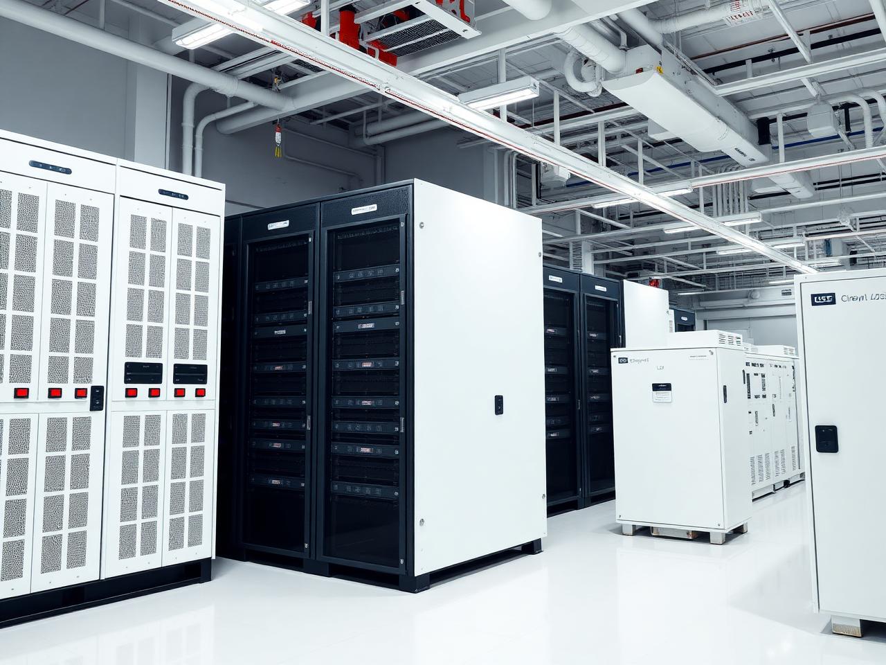
Mission-critical power infrastructure
Utility intake to rack PDU, engineered for continuous availability.
Utility & MV
- Grid connection
- Utility coordination
- MV substations
- Transformers
LV distribution
- Main LV switchboards
- Busduct
- PDUs
- RPPs
UPS
- Modular UPS
- Central UPS
- Distributed UPS
- N+1
Generators
- Standby generators
- Synchronization
- Fuel systems
- Bulk fuel tanks
Battery technology
- VRLA
- Lithium-ion
- Battery monitoring systems
Protection & energy
- Earthing
- Lightning protection
- Harmonic mitigation
- Power quality
Section 07
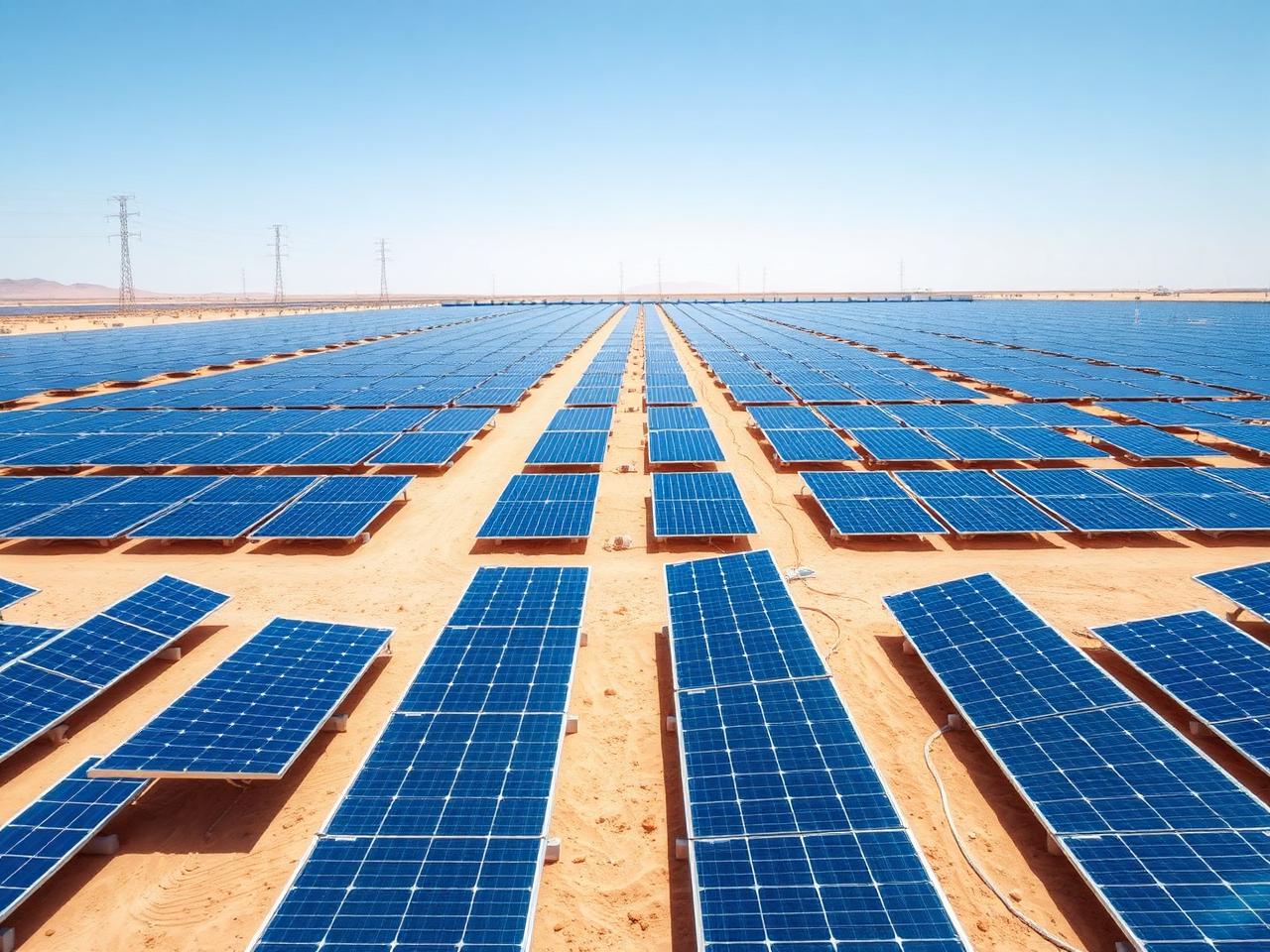
Precision cooling for every workload
Conventional precision cooling and liquid architectures for high-density AI halls.
Air cooling
- CRAC
- CRAH
- Chillers
- Cooling towers
AI / high-density cooling
- Direct-to-chip liquid cooling
- CDU systems
- Liquid distribution
- Rear-door heat exchangers
Design services
- CFD analysis
- Thermal modeling
- Airflow optimization
- Heat load calculations
Section 03 & 08
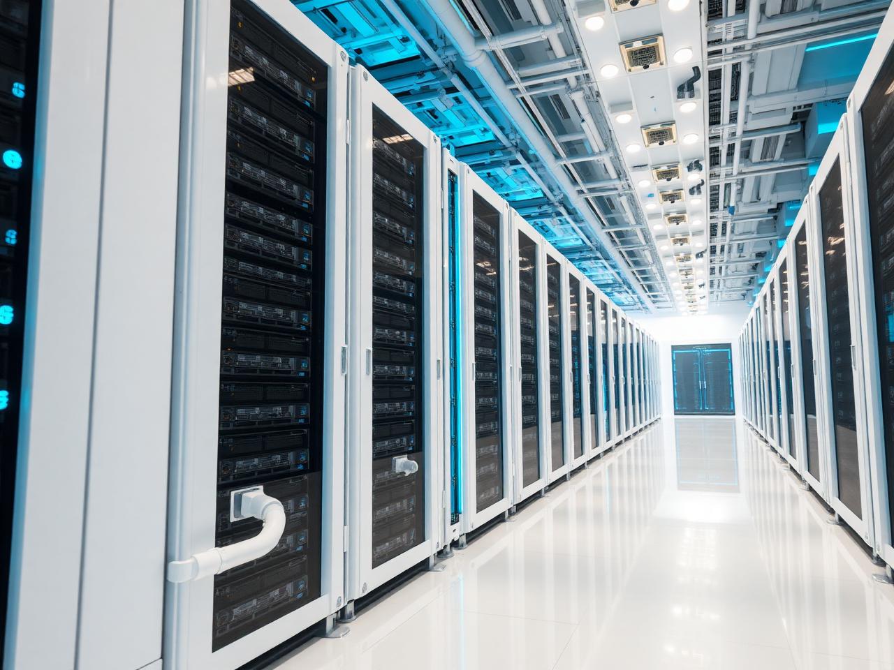
AI-ready infrastructure
Built for the next generation of accelerated computing.
AI facilities demand far higher rack densities, electrical capacity and heat rejection than conventional enterprise halls — TECH21 engineers the power, cooling, fabric and storage together.
GPU compute & racks
- GPU cluster design
- NVIDIA infrastructure readiness
- AMD GPU infrastructure readiness
- High-density rack engineering
- 30 kW rack environments
- 50 kW rack environments
- 80 kW+ rack environments
- 100 kW+ rack engineering
Fabric & storage
- GPU fabric
- InfiniBand
- High-speed Ethernet 100G–800G
- RDMA
- AI storage
- High-performance parallel storage
- NVMe and object storage
Power, cooling & operations
- Liquid cooling
- CDUs
- High-density electrical distribution
- Power quality
- AI cluster orchestration
- GPU monitoring
- AI security
- DCIM integration
AI reference architecture
AI compute to users
Energy & sustainability
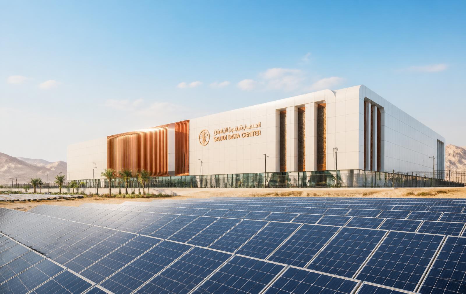
Solar PV inside the data center energy strategy
TECH21 integrates photovoltaic generation with the facility's electrical architecture — reducing grid dependency, lowering operating energy cost and supporting Saudi Vision 2030 sustainability targets, without compromising the reliability of critical power paths.
PUE
Improved power usage effectiveness
CO₂
Reduced operational emissions
OPEX
Lower long-term energy cost
2030
Aligned with Saudi Vision targets
On-site solar generation
Rooftop, carport and adjacent ground-mount PV arrays serving non-critical and support loads, configured for self-consumption or net metering per utility requirements.
Hybrid grid integration
Coordinated grid, PV, generator and UPS topology with switchgear and controls engineered to preserve dual-path distribution and required transfer times.
Battery energy storage
Storage for load shifting, peak shaving and transition coverage, with sizing studies plus dedicated safety, ventilation and fire protection design.
Measurement & efficiency reporting
Live PV yield and facility consumption metering inside DCIM, with PUE, carbon and renewable-share reporting for stakeholders.
The achievable renewable share is defined per project after site, load and utility studies. Critical IT loads remain protected by the approved primary power sources at all times.
Request a data center energy studyInteractive tool
PV sizing & energy strategy estimator
Set your expected IT load, efficiency target and available area to see an indicative solar array size, energy contribution, savings and storage allowance for your data center. Results update instantly.
Indicative results
Total facility load
1,400 kW
Annual consumption
12,264 MWh / yr
Recommended PV capacity
1,752 kWp
Array area required
10,512 m²
Annual PV generation
3,066 MWh / yr
Achieved renewable share
25.0 %
Annual energy cost saving
981,120 SAR
CO₂ avoided per year
1,686 t / yr
Suggested battery storage
420 kWh
Indicative PV CAPEX
4,905,600 SAR
Simple payback
5.0 years
Available area is sufficient for the modelled array.
Request a detailed energy studyAssumptions
- Specific yield of 1,750 kWh per kWp per year for a fixed-tilt array in Saudi Arabia, including soiling, temperature and system losses.
- 6 m² of installable area per kWp, covering module rows, spacing, walkways and maintenance access.
- Continuous operation at the entered load for 8,760 hours per year; no seasonal or ramp-up profile applied.
- Facility load calculated as IT load multiplied by the target PUE.
- Indicative turnkey CAPEX of 2,800 SAR per kWp for supply, installation, protection and commissioning.
- 0.55 kg CO₂ avoided per kWh of grid electricity displaced.
- Battery storage sized for 15% of facility load over 2 hours of peak shaving.
- Renewable share is capped at 60%; critical IT loads remain served by the approved primary power sources.
- Simple payback excludes financing, escalation, incentives, O&M and net-metering credits.
Disclaimer
This estimator provides indicative, non-binding figures for early planning only. It is not an engineering study, a design document, a performance guarantee or a commercial offer. Actual capacity, yield, savings and cost depend on site solar resource, structural and land constraints, utility and grid-connection requirements, protection and power-quality studies, equipment selection and market pricing at the time of tender. TECH21 confirms all values through a project-specific feasibility and energy study.
Section 09
From the rack to the cloud
Compute & platforms
- Server architecture
- Compute
- Virtualization
- Private cloud
Storage & continuity
- Storage
- SAN
- NAS
- Object storage
Section 10
Network & telecom infrastructure
Switching & fabrics
- Core switching
- Spine-leaf architecture
- Data center fabrics
- LAN
Connectivity
- Internet connectivity
- Carrier diversity
- Meet-Me Room
- Cross-connects
Cabling & speeds
- Structured cabling
- Cat6A
- Fiber OM4 / OM5
- OS2 fiber
Section 11
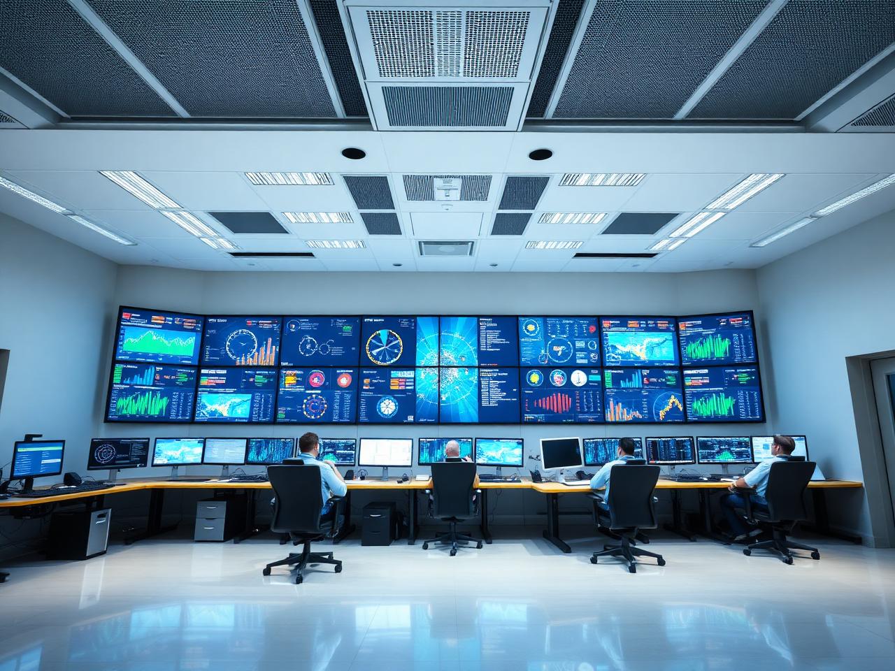
24/7 Network Operations Center
NOC escalation levels (L1/L2/L3) describe operational support — distinct from facility Tier classification.
NOC design
- NOC architecture
- Control room design
- Video walls
- Operator consoles
Platforms
- NMS
- EMS
- DCIM
- BMS dashboards
Operations processes
- Incident management
- SLA management
- Performance monitoring
- Capacity monitoring
NOC support levels
- L1 — Monitoring and initial response
- L2 — Technical diagnosis and resolution
- L3 — Senior engineering / vendor escalation
Sections 12–13
Security Operations Center & physical security
SOC capabilities
- Cybersecurity monitoring
- SIEM
- SOAR
- Threat detection
Physical security
- Perimeter security
- Anti-ram barriers
- Bollards
- CCTV
Section 14
Fire & life safety
Detection & suppression
- Very early smoke detection / aspirating detection
- Fire alarm
- Clean-agent suppression where appropriate
- Pre-action sprinkler systems
Life safety & compliance
- Emergency exits
- Emergency lighting
- Fire-rated construction
- Civil Defense coordination
Sections 15–16
The intelligent data center
DCIM, BMS and EPMS integrated into a single operational picture.
DCIM
- Rack capacity
- Power
- Cooling
- Space
BMS
- HVAC
- Temperature
- Humidity
- Leak detection
EPMS
- Utility
- Transformers
- Generators
- UPS
Facilities we plan
- Data halls
- Meet-Me Rooms
- NOC / SOC / command center
- UPS and battery rooms
Sections 17–18
Prove it before it goes live
Structured testing, commissioning and migration to a controlled go-live.
Testing & commissioning
- Factory Acceptance Testing
- Site Acceptance Testing
- Pre-functional testing
- Functional testing
Migration & go-live
- Migration planning
- Risk assessment
- Dependency mapping
- Server and storage migration
Sections 19 & 21
Operations, maintenance & deliverables
24/7 services
- Facilities Management
- NOC
- MEP maintenance
- Preventive maintenance
Studies & design documents
- Feasibility report
- Site-selection report
- Concept design
- Basis of Design
Engineering deliverables
- Network architecture
- Rack layouts
- Single-line diagrams
- Cooling schematics
Commercial & handover
- BOQ
- Cost estimate
- Specifications
- Tender documentation
Turnkey delivery
Design • Build • Integrate • Operate
Standards & compliance
Engineered to applicable standards
Industries we serve
Mission-critical sectors across the Kingdom
Why TECH21
One team. Every discipline.
TECH21 provides clients with one coordinated project interface across multidisciplinary data center engineering and technology packages.
Let's build
Build your next data center with TECH21
From an enterprise Tier II facility to a mission-critical Tier III/IV campus or next-generation AI infrastructure, TECH21 can support the full project lifecycle.
Data Center Capability Statement
A printable overview of TECH21 data center engineering, delivery and operations capability.
Request the capability statement